I went through a couple of small-scale iterations to get familiar with all of the pieces. This is the first full-sized build that is completely software controlled. The previous versions relied on outlet timers to control watering and our SmartThings hub for the lights. Version 1 uses ThingsBoard, a Raspberry Pi, and a dedicated Hubitat controller.
One big disclaimer: I have no background in electronics or hardware engineering. What I’m describing here might not be a correct (much less good) way to assemble such a system.
Aeroponic Hardware
I’m using the standard suite of DIY aeroponic components. Nearly every tutorial I’ve seen uses some variation of these components:
- 3x Aquatec CDP 8800 booster pumps
- 3x PAE TP-16P 4gal accumulator tank
- 3x US Solid USS2-00072 24v Solenoids (cheaper ones are available)
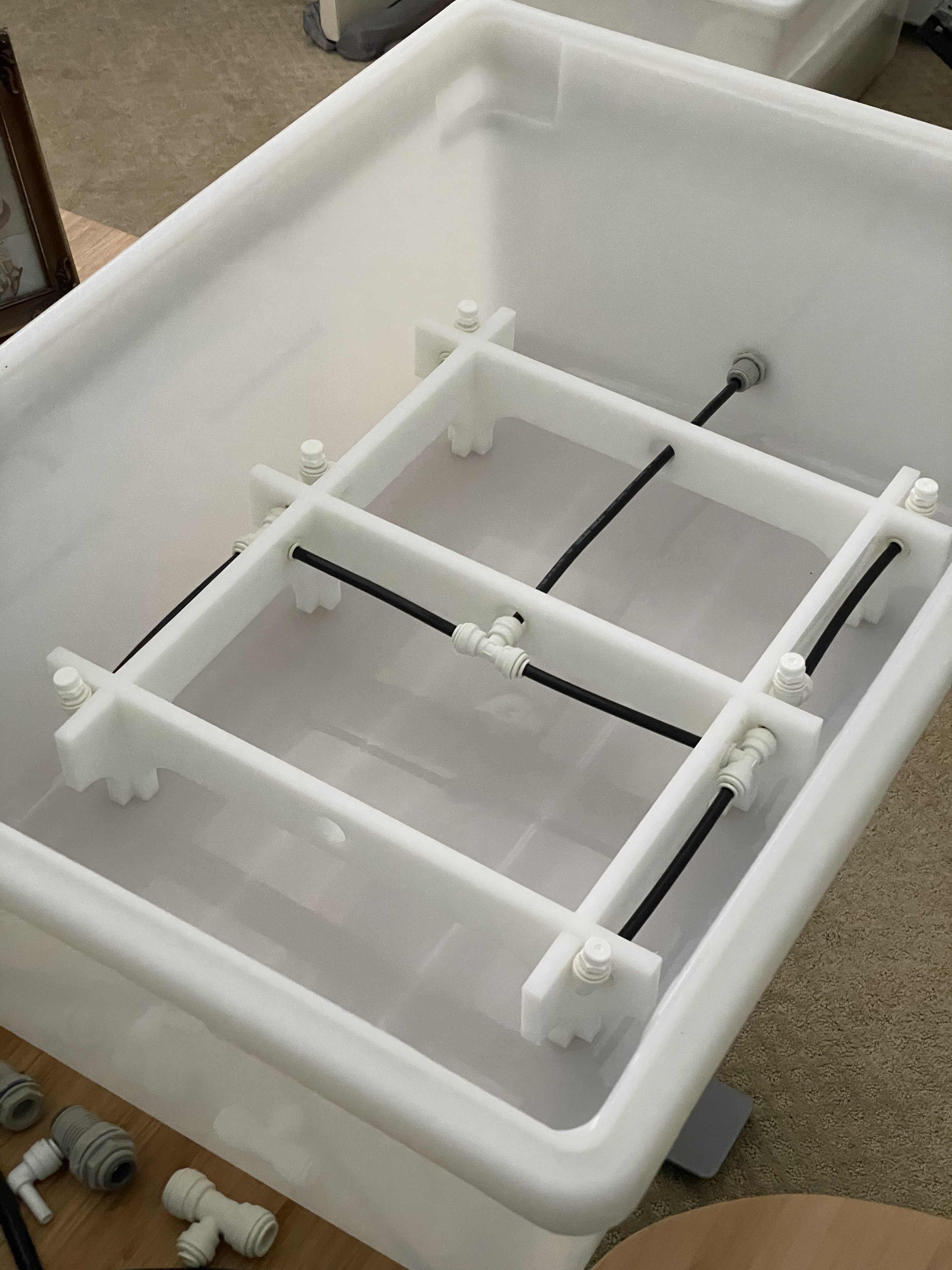
- Tefen 1/8″ NPT 1 GPH Fog Nozzles
- 3x Spider Farmer SF4000
- 3x DMFit 100mesh strainer
- 3x John Guest 3/8″ Check Valve
A 3-gallon food-safe bucket serves as the nutrient reservoir. The tank connects to a strainer and check valve before feeding into the Aquatec boost pump. An inline sediment filter catches all the tiny bits that make it past the strainer.

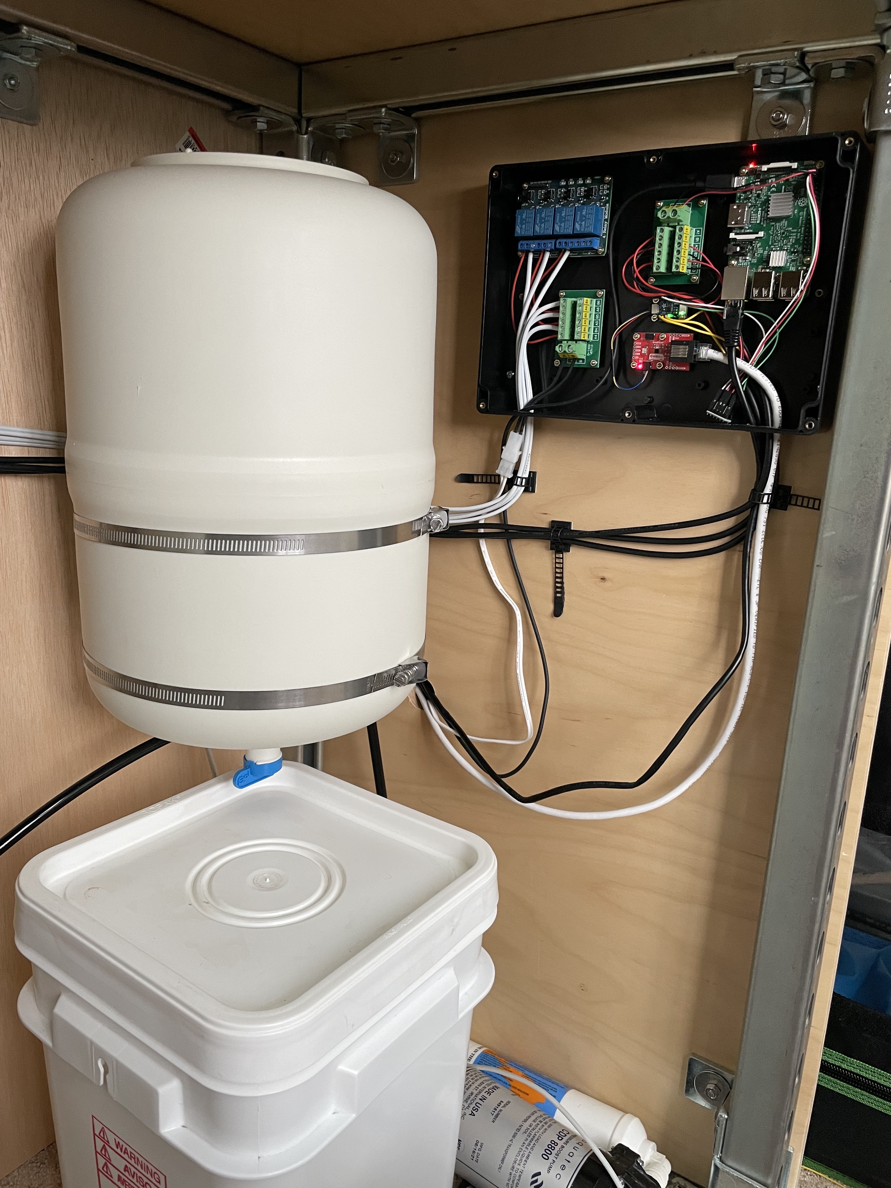
The accumulator tank is connected between the sediment filter and pressure sensor to smooth out demand on the pump. Without a tank the pump would be constantly kicking on and off as the nozzles spray. You can get away with a very small tank, but the larger one means that the pump kicks on less frequently (though for a longer period).
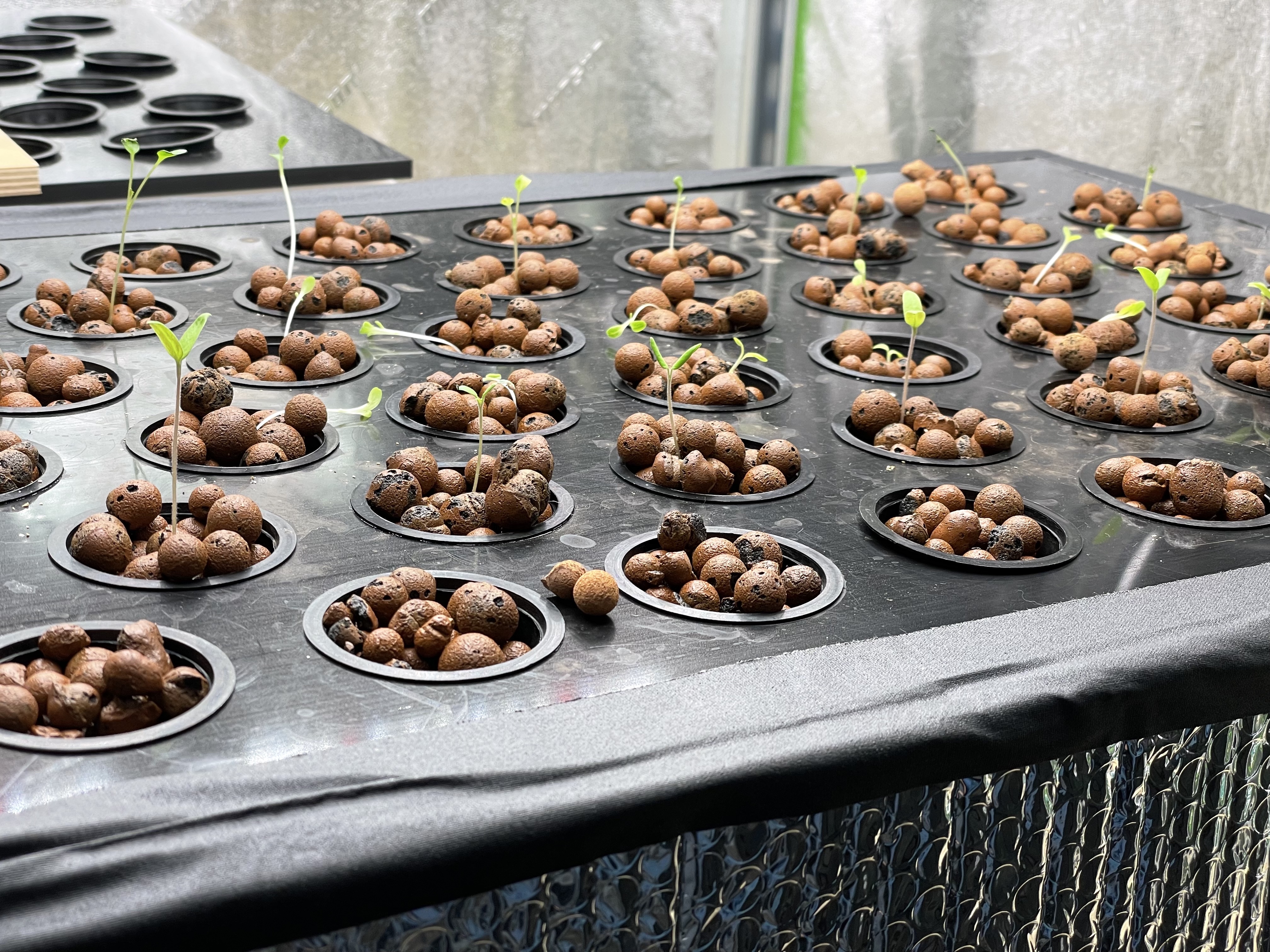
At the moment there’s only one chamber getting the seedlings started, but three more chambers will be online shortly. Two growing leafy greens will sit below the seedling chamber. The third chamber is for tomatoes and will have the full height of the tent available.
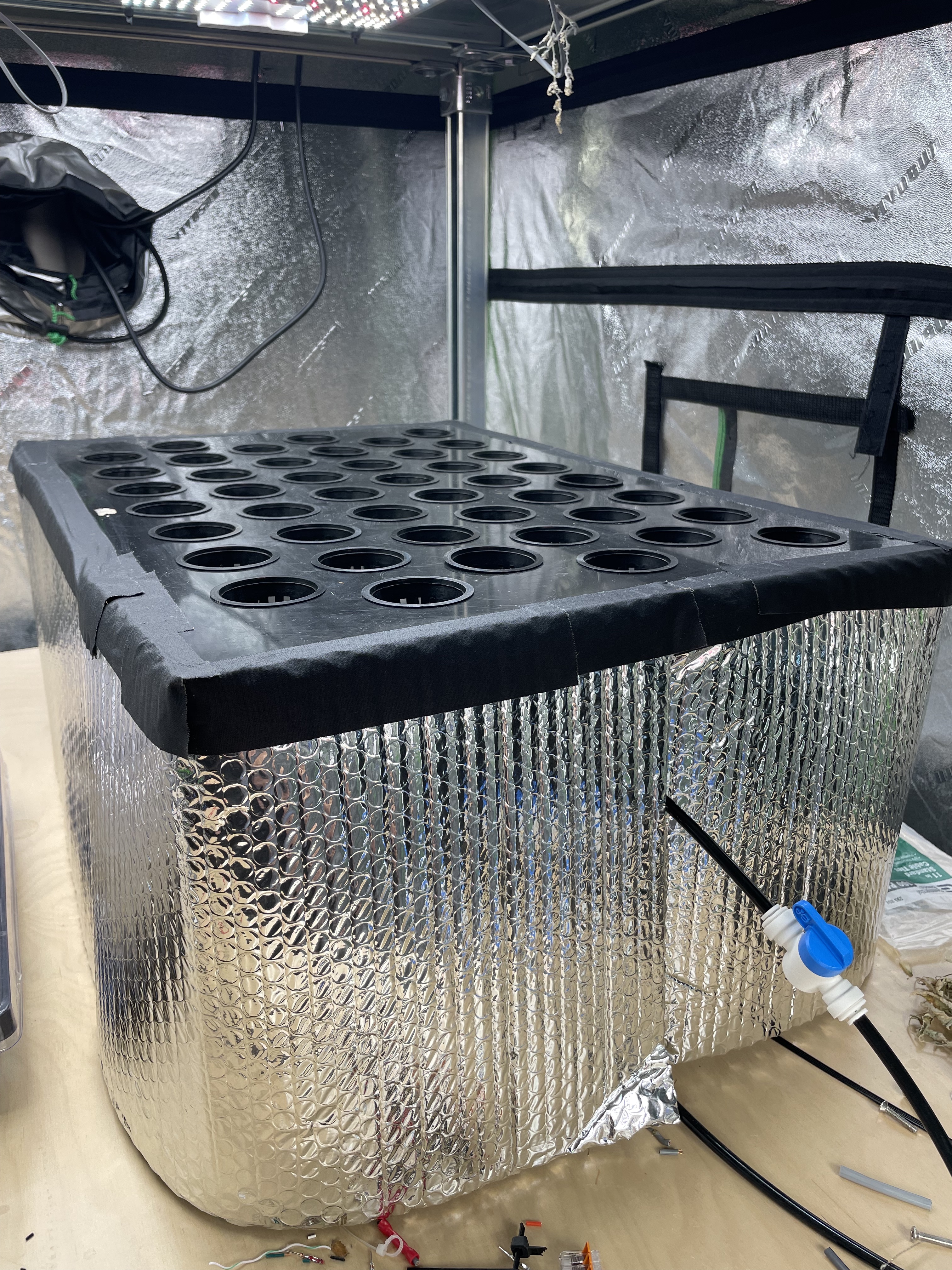
The seedling chamber is a standard HDPE bin with a lid that I had CNC cut by eplasitcs.com. They happen to be local so it wasn’t terribly expensive. I’ve since made more lids with a hole saw and a router with a template pattern bit. You can rough cut undersized holes with the hole saw and then route them to final size with the pattern bit.
Control Hardware
An Intel NUC serves as the control center for the garden. You could probably get away with something like a Raspberry Pi, but I like having the the memory and CPU headroom. In this case it has a 10th-gen i3 with 16gig of ram, but it supports up to 32gig.
A Hubitat Elevation Model C-7 is used for controlling the SpiderFarmer lights by way of Samsung SmartThings outlets. I didn’t feel comfortable playing with 110v through a Sainsmart relay so this seemed like the next-best option. The hub is connected by ethernet to the NUC through a Netgear switch
Each “pod” in the garden (there’s only one right now) is controlled by a Raspberry Pi 3B attached to the following:
- Adafruit SCD30 – Environmental monitoring
- Adafruit ADS1015 ADC / Honeywell MIPAN2XX100PSAAX – Tank pressure monitoring
- SparkFun Logic Level Converter
- Sainsmart 4-channel relays – Pump and solenoid controls
- Mean Well GST120A24-P1M – 24v solenoid power supply
- Aquatec power supply – Pump power
- 3x 2×6 Terminal Block Module
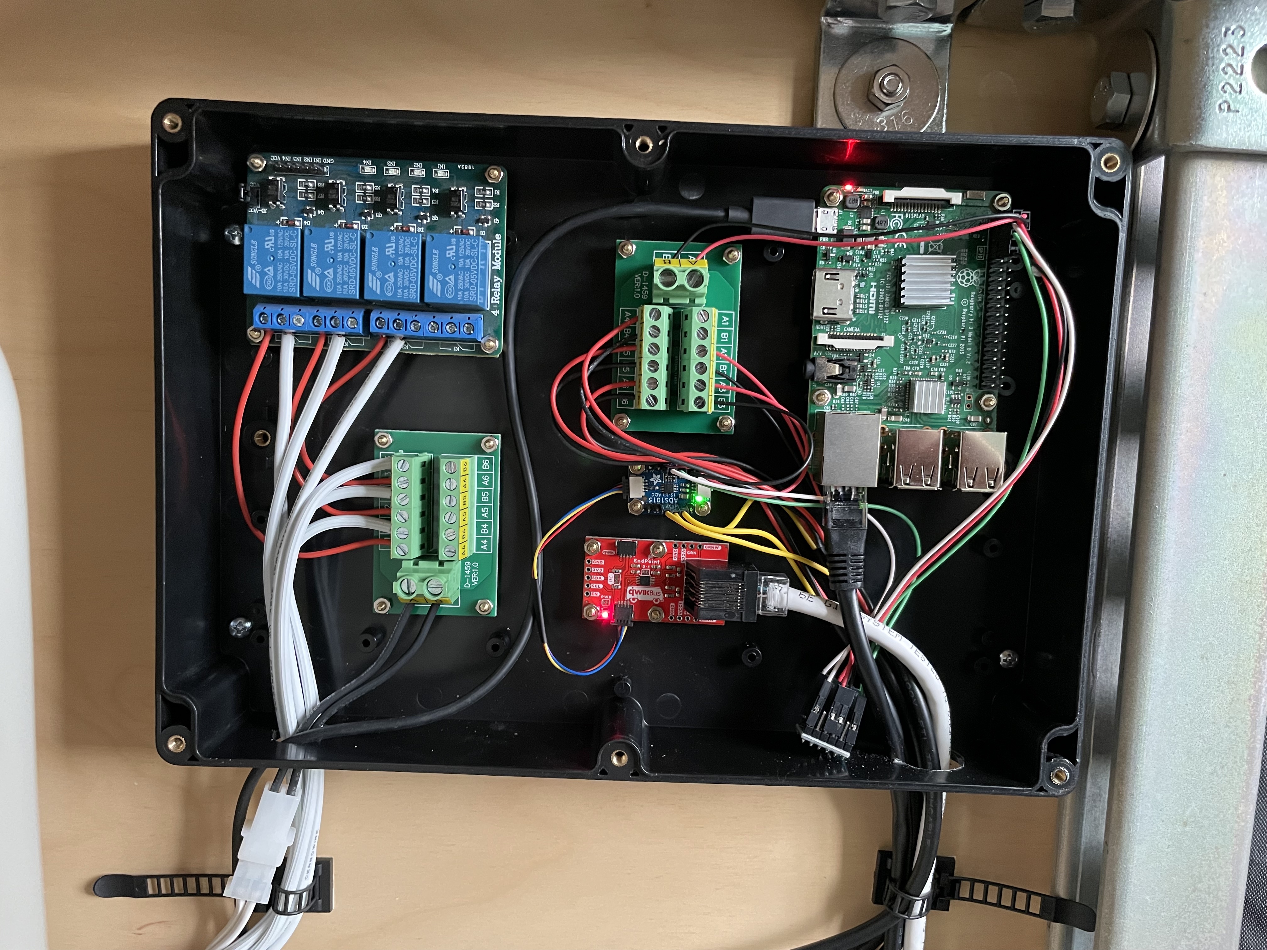
Douglas Crockford said “Everything is shit until it’s 3.0” and that’s proving true. It’s looking much better than the original DIPs stuck in a breadboard, but I didn’t quite nail the layout. The ethernet connectors are much too close, and I had to add a logic level converter after the fact. Still, progress is being made.
Something important to call out: The Sainsmart relays and the pressure sensors run at 5v but I2C on the Pi runs at 3.3v. Word on the street is that running 5v to the I2C pins will eventually fry the Pi. Using a logic level converter will shift back and forth between the 3.3v and 5v systems.
This setup evolved from a dinky little tent with a single timer and pump rather than being designed fully from scratch. The physical layout isn’t ideal. In particular, the solenoids and environmental sensors are far from the controller. I could easily run individual wires for each solenoid, but I2C doesn’t work well with cables longer than something like 3ft. The solution I found is the SparkFun QuiicBus. You can run I2C up to 200ft over Cat5. It only uses four wires and the others can be used to supply extra power.

The QuiicBus connects to the environmental sensor and an I2C GPIO expander that controls the Sainsmart relay. I’m fairly happy with how simple it was to wire up even though the control software is more complicated. I have to control some GPIOs directly from the Pi and the others through the I2C expander.
The NUC, Hubitat, and Raspberry Pi are all connected by ethernet through a Netgear switch.
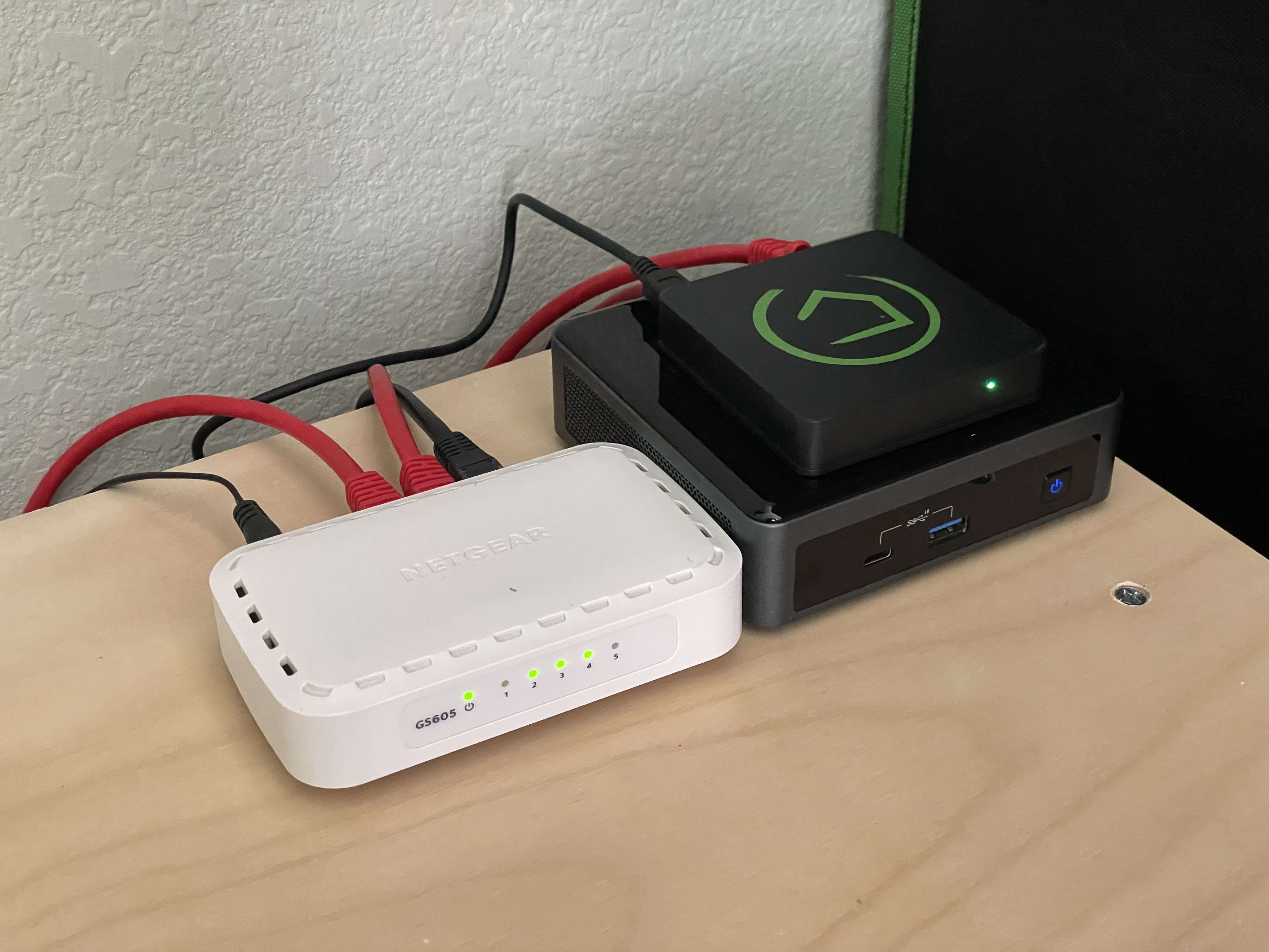
We have enough stuff connected to our home wireless network and I already had the network gear/cable. The NUC has iptables rules setup to forward the Hubitat ports to the NUC so that they’re accessible on the home network. We also have custom DNS setup by way of a PiHole so that all of the services are accessible by domain name rather than ip address.
Control Software
ThingsBoard runs in a Docker container that the Raspberry Pi communicates with over MQTT
The Raspberry Pi is running simple Python script that monitors tank pressure, schedules lights and watering, and turns on the tank pumps when pressure drops below the specified level. It also relays telemetry back to ThingsBoard and can receive configuration updates via ThingsBoard shared variables.
What’s Next
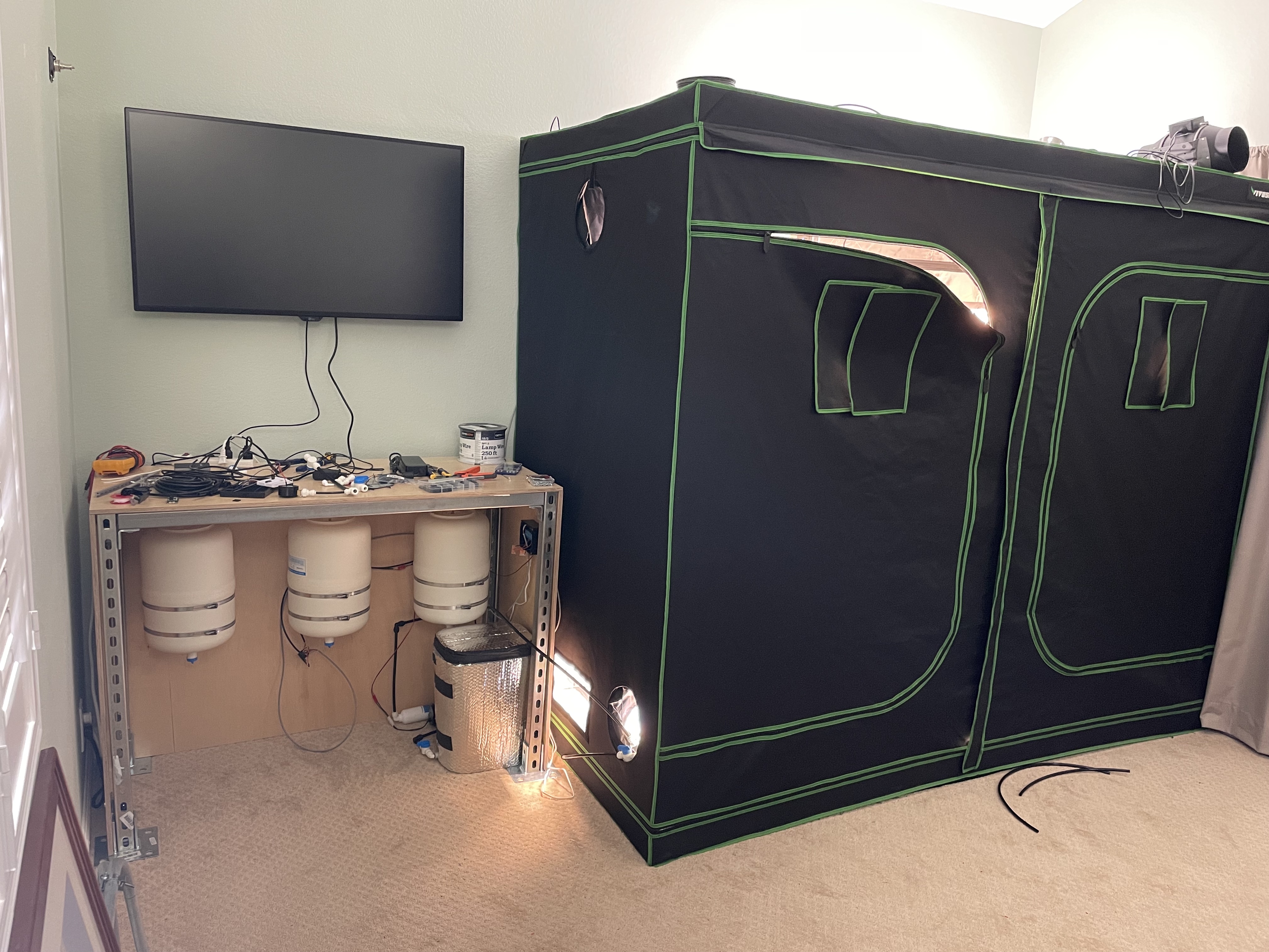
This build was great for getting familiar with all of the components, but it’s still not the most elegant or scalable. The biggest issue has to do with the layout. It’s up against a wall and the pumps, tanks, etc. are far from where the chambers/nozzles are. Keeping everything close would eliminate the need for the QuiicBus and a lot of the wiring/tubing.
After a few successful grow cycles the plan is to scale up to about 100ft^2 of grow area. The tanks are probably overkill for the number of nozzles we have, but the three beds have somewhat different nutrient requirements. I also quickly discovered that the reservoirs need to be below the bottoms of the growth chambers. The next build will either elevate the tent above the level of the reservoirs or I’ll find some kind of wide and short container for the nutrients.
Finally, it’s been a pain to have to refill the nutrient tanks so I’d like to move on to an automatic mixing strategy. A direct line to the reverse osmosis tank and peristaltic plumps plumbed directly to the nutrient bottles might do the trick.
